Tuesday, August 24, 2010

Oxygen Sensor Write-Up


Parts:

  • 1 x 14 pin LM324 Op-Amp.
  • Resistors = 1KR 0.5W (R2,R3,R4), 390R 0.5W (R5), 10KR 0.5W(R6), 270R 0.5W (R7) and 470R 0.5W (R8).
  • 2 x Capacitors (C1 + C2, Monolythic Dip C5K 1uF)
  • 3 x 1.8V LED (Green, Yellow and Red)
  • 3 x 1N4001 0.7V Diodes (D2, D3 and D4)
  • Zener Diode 9V1 (D1)
  • Vero Board 19x25
  • Jumper Wires
  • Power Wires = 12V Red, Earth Black and 1V Red
What it Does: Works as a tester for an oxygen sensor.

Calculations: Resistor Calculations. R2, R3, R4 = 12V-1.8V(LED) - 0.7V(Diode) = 9.5V/0.0095A(LED) = 1KR
R5 = 12-9.1V(Zener)/0.0095A = 390R (prefered value. answer was 305 ohms)
R6 = 10KR as stated in diagram (we use this to find the current for R7 and R8: 9.1V/10K ohms =
0.00091A)
R7 = 0.4V / 0.00091 = 470R prefered value (440 ohms)
R8 = 0.23V / 0.00091 = 270R prefered value (250 ohms)


How it Works:
Connect the positive of a 12V Vs to the 12V Red wire at the top right of the board and the negative wire of the Vs to the Earth Black wire of the board. Also connect a seperate 1V Vs to the 1V Red wire at the bottom right corner of the board and the negative to the Earth Black wire. Pin 4 of the IC is connected to 12V and Pin 11 is Earthed. Pins 2, 5, 10 and 13 are connected inbetween resistors R6 and R7 leading to Earth.

At first the current passes through the Zener Diode, Capacitor and R5 resistor limiting voltage to 9.1V at the positive rail. This then goes down to each LED having passed through 3 more resistors limiting current at the IC. These all lead to each Output pin of the IC. A Sensor Input that can be adjusted to delover 0V -1V is connected to terminals 3, 6, 9 and 12. When initially hooked up the Green LED will light up. When adjusted to 0.3V the Yellow LED lights up. Then when 0.6V is put through, the Red LED lights up.

Testing the Circuit:
Using a Voltmeter.
Each LED should read 9.9V when off.
Pins 2 and 5 should read 0.64V
Pins 10 and 13 should read 0.23V
Pin 11 should read near 0V as it is Earth.
Pin 4 should read 11.2V

Problems: As with everyone that everntually got this circuit to work I had not bridged Pins 2 and 5, and Pins 10 and 13 properly and not at the right points inbetween resistors. Once this problem was rectified my circuit still would not work apart from the LED's lighting up but not in correct sequence. This was because a jumper wire I had hooked up was touching another jumper wire. When I made sure both were no longer touching my circuit then worked as it was supposed to.

Reflection: If I were to repeat this task I would be much more careful with my jumper wire placement (less would be good aswell) and pay closer attention to the diagram for my wire placement with the resistors in mind.

Monday, August 23, 2010

Power Circuit Write-Up


Parts:
  • D1 1N4001 1A 100V
  • D2 1N4001 1A 100V
  • Zener Diode 5V1 400mW
  • 25V 33uF Capacitors x2
  • Voltage Reg. LM317T
  • R1 resistor 1KR 0.5W
  • R2 resistor 330R 0.5W
  • R3 resistor 100R 0.5W
  • LED 2.V 30mA
  • Jumper Wires x3
  • Red Wire 12V
  • White Wire 5V
  • Black Wire Earth
  • Vero Board
Whats its used for: Anything requiring a 5V Vs when only a 12V Vs is available up to 30V.

How it Works: This circuit only needs a voltage regulator and 3 resistors to work which means that everything else is there for protection.

With a 12V Vs connect the positive wire to the Red wire on the Vero Board and the Earth wire of the Vs to the Black wire on the Vero Board. Current will pass through the first 1N4001 Diode ,which has a forward bias voltage of 0.7V giving us 11.3V, a Zener Diode and a 33uF Capacitor , both of which function as protectors for the Voltage Regulator, current then hits the IN terminal of the voltage regulator. There is also an additional 1N4001 Diode in Reverse Bias providing extra protection to the Voltage Regulator.

In order to calculate the resistors needed I remembered that because the outut voltage was going to be 5V I could use any Resistors as long as their ohm values had a ratio of 1:3 for R1 and R2 and used the formula Vout = Vref ( 1 + R3/R2 ) and ended up with 1KR and 330R resistors for my ADJ circuit. Now getting 5V out of the OUT Terminal of the Voltage Regulator, current goes through a 33uF capacitor then my Red LED protected by a 100R Resistor ( R3 ) will light up. At the end of the circuit is 3 wires. My 12V out, my 5V out and my Earth coloured Red, White and Black.

Testing: With a Voltmeter. As long as you are getting 5V out of the 5V output and 12V out of your 12V output your circuit is working as it should.

Problems:
At first I realised my 1N4001 Diode in reverse bias didnt have a drill hole underneath it which I promptly included. Secondly I was only getting 3.3V from my OUT terminal of the VReg. After much fault finding and help from Carl it was discovered that I was using the wrong resistors for R1 and R2 in the wrong format. After switching to a 1KR for R1 and using the 330R for R2 i rearranged them in the format you can see in the picture. At this point i was still getting 3.3V. For a reason unknown to me the placement of my 5V out wire was affecting my readings as when I relocated it to right in front of the VReg I got 5V and my LED lit up.

Reflection: If I was to do this again I would double check my resistor calculation so as to not have the problems I had and after having learnt how to fault find properly double check the R1 and R2 resistor layout to make sure it would work properly.

Injector Circuit Write-Up


Parts:
  • Vero Board
  • Jumper wires x5
  • R1+R2 resistor 470R Correction : 0.5W
  • R13+R16 resistor 100R Correction : 0.5W
  • BJT Transistor NPN type BC 547 x2
  • LED 1 2V 5mm 30mA Yellow
  • LED 2 2V 5mm 30mA Red
What it does: ECU operated, switches injectors at high speeds.

How it Works: First of all the circuit must be connected to a Vs of 12V. This sends current through the Resistors and LED's to the Collector terminals each BJT.
In order for the LED's to operate current must also be sent to the Base terminal of either BJT from either 5V Vs'. This switches the BJT fully on (saturated) and thus lights up the LED. This 5V supply can be switched to either BJT so as to turn either LED simultaneously. To complete each circuit each Emitter terminal of the BJT's is Earthed at the 0V rail of the Vero Board.

Test Procedure: To test this circuit you must have a 12V supply and a 5V supply. The negative wires from both power supplies need to be connected to the negative wire on the board. The 12V positive wire is connected to the positive wire on the board. The 5V positive wire is placed on either the channel one or two wires of the circuit depending on whether channel you wish to activate the Yellow or Red LED. The yellow LED should light up when channel one is connected and when channel two is connected the Red will light up.

Calculations:
Finding the values of my resistors.

R1 = 12/0.03mA = 400 ohms (470R)

R2 = 5 - 0.7 = 4.3/0.09A = 47 ohms (100R)


Problems:
No problems or faults were encountered whilst making this circuit.

Reflection: If I were to do this circuit a second time I would not do it any differently apart from seeing if at all the amount of space on the board could be reduced and not drill my holes as large as I did.

Tuesday, August 3, 2010

Experiment #2: Diodes

In experiment #2 I was asked to identify the anode and cathode of my LED and 1N4007 Diode using my multimeter.

My readings were LED: Anode - OL Forward Bias
Cathode - OL Reverse Bias

1N4007: Anode - 695mV Forward Bias
Cathode - OL Reverse Bias

In able to identify these without a multimeter, on the LED, I would have looked for the longest stem, it being the Anode, and the shorter being the Cathode. For the 1N4007 the end of the Diode which has the gray stripe would be the Cathode and the opposite being the Anode.


Calculate the first value of current flowing through the diode, now measure and check your answer.

Calculated: 5V/1000R = 5mA
Measured: 4.78mA

Is the reading as you had expected?: Yes, I expected to get 5mA if not just slightly less than 5mA.

Calculate the voltage drop across the diode, now measure and check your answer.

Calculated: 695mV ( taken from previous question )
Measured: 665mV

Using the data sheet, What is the maximum value of the current that can flow through the given diode?: 1A

For R = 1KR. What is the maximum value of Vs so that the diode operates in a safe region?
: 1000V

Replace the diode by an LED & calculate the current, then measure and check your answer.

Calculated: 5V/1KR = 5mA
Measured: 3.41mA

What have you observed?: Because the voltage has remained constant and the current has decreased, the Resistance must have increased when I switch the Diode with the LED.

Notes

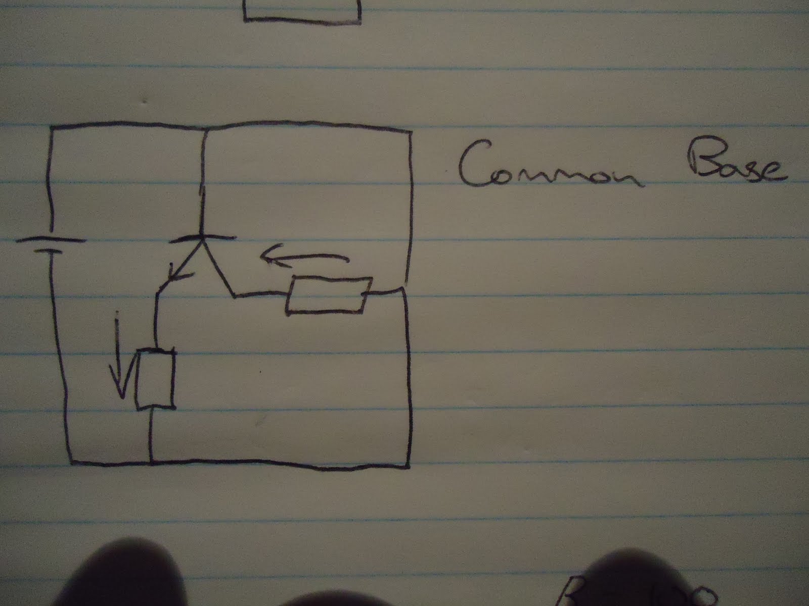
Here are some pictures of notes taken during lessons and some from my workbook and two of my home power supply that I made in class.